Link to the original blog post with a nice text/pictures layout.
The problem:
- kids keep forgetting to carry the key to unlock the front door. They never forget to carry their phones though.
The solution:
- unlocking the front door using a mobile phone
HW parts:
- front door with magnetic solenoid relay
- ESP32 board with a single relay (SZHJV)
- USB2TTL adapter
- 24V power supply (Meanwell MW HDR 30-24)
- 5V power supply (didn’t need it)
- 6A circuit breaker (Doepke)
- some wires
- NFC sticker (special type for sticking it to the metallic surfaces)
- Aqara Door/window zigbee sensor
SW:
- #HomeAssistant (server)
- Home Assistant Companion App
- #ESP32Home
The process:
- I installed a wall box near the front door, under a nearby electrical socket (see below)
- When the company installed the front door, I asked them to install a UTP cable from the door lock mechanism to the socket.
- Bought the materials above (Aliexpress for the boards, Conrad for the power suppy).
- Connected the mains to the breaker (for emergency switch-off)
- Connected the cables from the breaker to the 24V power supply
- Connected the cables from the power supply to the ESP32 board, door solenoid relay and ESP32’s relay. Luckily, I didn’t need to install 5V power supply for the ESP board, because it also works with 24V.
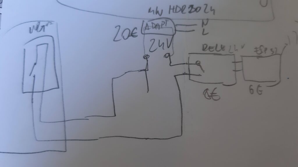
Here’s the doodle of the connecting scheme:
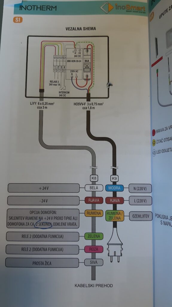
Here’s the original connecting scheme from Innotherm (door manufacturer), in Slovenian: It was useful because it reveals which power supply is appropriate (Meanwell MW HDR 30-24).
7. Fitted everything in the wall box. It was too shallow! I couldn’t hide all the junk with the flat cover that came with a box.
Before fitting:
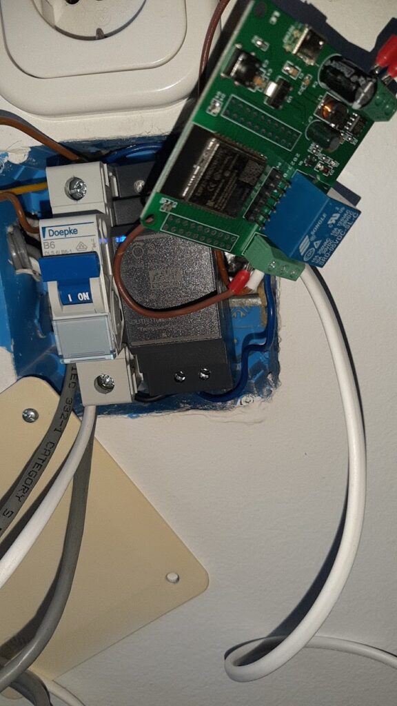
Everything nicely fit in a box:

8. I designed and 3D printed a new cover in TinkerCad:
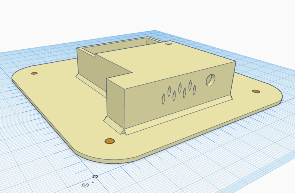
10. After a 3rd try (of 3D design and printing), all measures were finally correct and I could cover the box (Mastodon post):

11. Flashed ESP32 board with ESPHome*, added it to Home Assistant.
(*Actually it wasn’t that simple. The board doesn’t have a data USB connector. I had to buy USB2TTL adapter. I was bitching about it here.)

Nevertheless, after the firmware update, I edited .yaml for the board so it exposes:
Main entity:
- Switch (for controlling relay), connected to GPIO16
Misc. entities:
- LED light (connected to GPIO 23, to signal when the door is opened)
- Wifi sensor (for checking the power of Wifi signal, because the esp board is located in a wall box)
- Uptime (to see the time since the last esp board reset)
- Restart switch (to remotely restart the board if needed – but until now it wasn’t needed)
.yaml code for ESPHome (gathered from various websites, mainly from ESPHome):
... skipping the first part, wifi connectivity, substitutions etc.

light:
  - platform: status_led
    name: "ESP32-rele01-vrata Led"
    restore_mode: ALWAYS_OFF
    pin:
      number: GPIO23
      inverted: False

switch:
  - platform: gpio
    pin: GPIO16
    name: "Door lock switch"
    inverted: False

  # The following can be omitted
  - platform: restart
    name: ${devicename} restart

sensor:
  - platform: wifi_signal
    name: ${devicename} wifi signal
    update_interval: 600s

  # human readable uptime sensor output to the text sensor above
  - platform: uptime
    name: ${devicename} Uptime in Days
    id: uptime_sensor_days
    update_interval: 60s
    on_raw_value:
      then:
        - text_sensor.template.publish:
            id: uptime_human
            state: !lambda |-
              int seconds = round(id(uptime_sensor_days).raw_state);
              int days = seconds / (24 * 3600);
              seconds = seconds % (24 * 3600);
              int hours = seconds / 3600;
              seconds = seconds % 3600;
              int minutes = seconds /  60;
              seconds = seconds % 60;
              return (
                (days ? String(days) + "d " : "") +
                (hours ? String(hours) + "h " : "") +
                (minutes ? String(minutes) + "m " : "") +
                (String(seconds) + "s")
              ).c_str();

time:
  - platform: homeassistant
    id: homeassistant_time

# Text sensors with general information.
text_sensor:
  # Expose ESPHome version as sensor.
  - platform: version
    name: $devicename Version
  # Expose WiFi information as sensors.
  - platform: wifi_info
    ip_address:
      name: $devicename IP
    bssid:
      name: $devicename BSSID

  # human readable update text sensor from sensor:uptime
  - platform: template
    name: Uptime Human Readable
    id: uptime_human
    icon: mdi:clock-start
12. I’ve put an NFC sticker on the door.
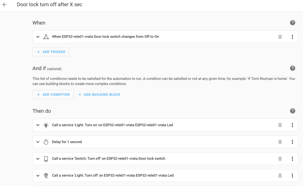
13. Wrote 2 simple automations that open a relay when the phone touches the NFC sticker and closes it after 1 second:

2nd automation switches the relay off after 1 second (also blinks the red status led on the ESP board):
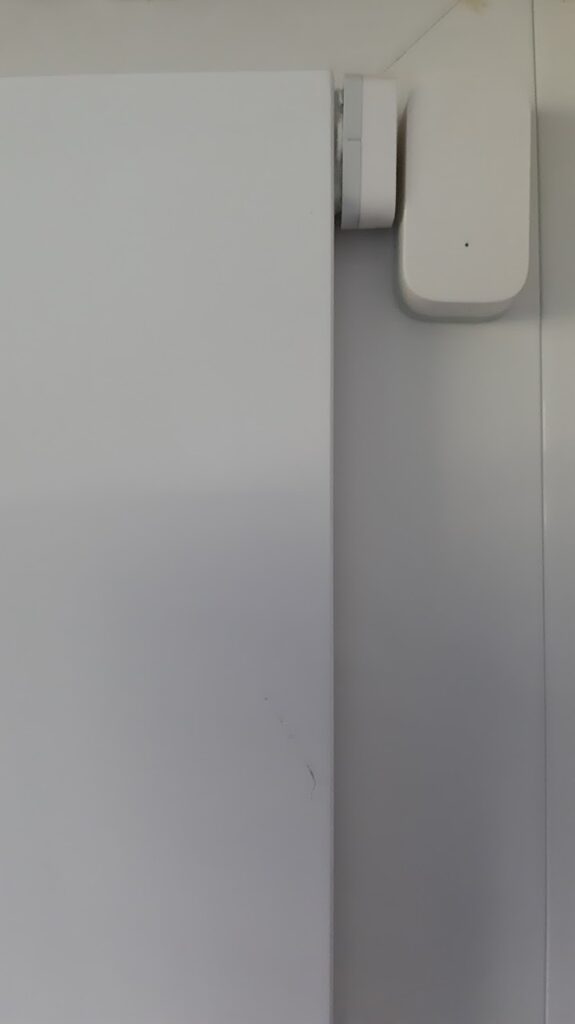
14. Added Aqara Door sensor to the door and connected it my existing Zigbee network using Zigbee2MQTT. It’s for logging when the door is open and for turning on the red status LED on the ESP32 board when the door is opened.
15. Added a new control dashboard in Home Assistant for tracking what’s going on with the door:

Conclusion
After 6 months, it works great. Kids are satisfied and me too, because this is one of the first usable HomeAssistant projects that involve some electronics and physical devices. It works in 99% of cases.
There are some issues with it though:
- The ESP32 board sometimes reboots after unlocking. It seems that the door solenoid relay draws too much current and the voltage from the power supply drops momentarily. Probably I need to add a capacitor to the board power input to smooth the voltage. This is not a big issue, because the board starts working normally after 3 or 4 seconds after the reboot.
- Once or twice it happened the esp board relay got stuck in an OFF state. I had to hit it gently with a screwdriver to unstuck it. After that, I reduced the time the door solenoid is opened from 2 to 1 sec. Not sure if it will help. Maybe it’s just a bad relay.
- Several times the wifi was down and the board couldn’t communicate with the Home Assistant. It looks like my telco provider’s router is not the best one and it freezes sometimes. Probably I need to buy a better wifi router.
TODO
I have several ideas on how to upgrade the unlocking mechanism:
- unlocking with a fingerprint
- unlocking with facial recognition
Disclaimer
The links to the products are not affiliate links and I don’t receive any compensation for linking.
The code and the ideas are mostly from HomeAssistant and ESPHome community forums.
Thread on Mastodon
https://mastodon.social/@po3mah/111306836068315890
Update 1: the relay broke
Sometime in June 24 (after hald a year of installation), a relay broke. I hear the relay click sound when I activate the relay, but the door stays closed. I measured the resistance of the relay and it’s always disconnected. The door relay is fine, I connected it directly and it opened.
Probably I have to add a capacitor and/or rectifier diode to a circuit to prevent voltage swings and reverse voltage/current. When the solenoid closes probably it induces a current…
Update 2: fixing the broken relay
… in progress … (I’m not an electronics professional – if there are mistakes, please correct me)
What kind of circuit I need to prevent the voltage drop when solenoid opens and reverse current when closes?
Probably this is the circuit I need (I have a relay instead of transistor):

Source: https://electronics.stackexchange.com/questions/167484/electrolytic-capacitor-in-solenoid-circuit
So how big capacitor should I add?
i=CdU/dt => C=Idt/dU =>
I=250mA (ESP max current draw)
dt=2 sec. (time of relay open)
dU=24V (initial voltage of transformer) – 10V (allowed voltage drop, not sure, ESP works from 7V up)
C=0.25A * 2 sec./ (24V-10V) =>
C= 0.035 F = 35 000 uF = 35 mF
This sounds … pretty big, when I googled this big capacitors I became sceptical if the calculation is correct. This big capacitor costs ~15€… Probably this is not correct. Maybe I misunderstood which t should be used in the formula (probably not the duration of solenoid being opened, but the time of change from open-close and vice versa). If I speculate the time of the solenoid switch is 0.1s then C=1041uF which sounds more realistic. But I’m still not sure if I’m on the right path.
After some googling I found out I have to use another formula. It’s an energy management problem, not (directly) a relation between C, I, U and t.
The rabbit hole of solenoids is deep (1, 2, 3).
So the formula for energy stored in solenoid is:
E=1/2 * C * U2
… but I don’t know how much energy is stored by the solenoid.
(…to be continued)
….
Another thing I have to put in the circuit is a flyback diode / rectifier diode like 1N400x to prevent reverse voltage.
(… to be continued …)
Leave a Reply